The eTap Blipbox and the Cervelo P5
In which I grab the soldering iron and splice together wires and plugs to place the 'brains' of the eTap system deep in the bowels of my TT frame!
Earlier this year, I travelled to Wales for a Team Grumpy reunion of sorts, in the form of a 2-up team time trial. This was a ‘sporting course’, so I took along my Cervelo P3, currently equipped with 11-speed eTap Red gears. By the time the bike had been in and out of the car a few times, one of the blipbox ports had stopped working (this happened before, with the P5).
I had the blipbox repaired by the Turbo Trainer Doctor - as I understand it, the sockets to which the gear switches connect are mounted on the circuit board, and it’s likely that one of them got tugged by the wire.
This got me thinking - I had the same gear system on my Cervelo P5, with the blipbox mounted on top of the Aduro TT bar stem. It’s a bit exposed there - to wire tugging, rain, and sweat. It’s stood up pretty well over the years, though it did have one malfunction that necessitated a replacement under warranty for a similar defect that I saw this year with the P3. I came up with a bit of a madcap plan…
Concealing the eTap Blipbox and wires inside the P5
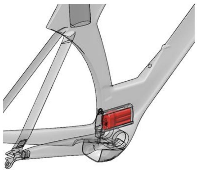
I’d known for a while that the original P5 frames have a ‘hidden compartment’, located just above the BB area and opening via a hatch on the rear of the seat tube. It’s designed to take DI2 batteries, and I figured if I extended the blipbox cables, I could pace the blipbox in there.
In doing this, I wanted to minimise the number of cables passing inside the frame. Because the blip and clic switches seemed from my internet searches to be merely dumb momentary switches, I reckoned that two switches could be connected to a single port on the blipbox.
I also wanted this arrangement to be as reversible as possible, so I used some tiny JST connectors to set up cabling.
- I began by cutting the eTap plugs (which appear to be proprietary, as no-one on the internet has reported being able to source them) from each switch, leaving enough cable to solder connectors. I then soldered a JST connector to each switch,
- I soldered two of the JST connectors to each of the main wires, setting up a Y-arrangement.
- To the other end of the main wires, I soldered another JST connector.
- Another JST connector was soldered to the two eTap plugs.
- I assembled the wiring to verify everything worked OK. I used heat shrink insulator to ensure all solder joints and connectors were as robust and waterproof as possible.

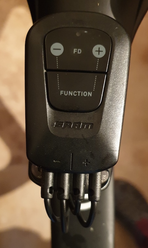
With the ‘Y-shaped’ cable arrangement, both downshift switches connect to a single port on the blipbox, as do the two upshift switches. The two empty ports have the dummy plugs supplied with the blipbox.
With all that none, I needed to see how to get the wires down to the hidden compartment. I’d seen in the P5 manual that behind the head tube there are three round ports for brake and gear cables, and a rectangular one that can be used for wiring to the hidden compartment.
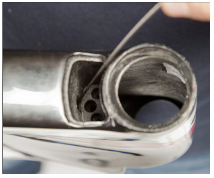
The problem?
My P5 doesn’t have the rectangular opening. I was all prepared to get out the trusty Dremel and make one, but of course I don’t have gear cables running through the frame, so I tried using the routing for gear cables. This was dead easy with the Park Tool internal cable routing kit. At least it was easy getting the cabling through the frame - it was a bit more of a fiddle getting the cabling through the base bars. especially as I had just replaced the hydraulic hose for the front brake because I’d removed the fork to inspect it. As an aside, inserting the barbed fitting in a Magura hose is much easier with one of these (relatively) cheap pin driver I’d bought for this purpose from Amazon a year or so ago. Makes the whole task pretty easy. The hose cutter works well, too.

By the time I’d got everything routed and installed, I was well into day three of tinkering - this wasn’t really a quick job. I took the bike out for a short 5 mile test rider, and confirmed that all was working OK.
I’ve since ridden a 10 mile club TT with it, with no issues. I washed it down afterwards, with no obvious issues with the newly configured electrics.
I imagine this approach could be used to place the blipbox internally in a number of TT bike frame designs. There's an option for the newer 12-speed eTap AXS to use smart shifter buttons which mean a blipbox isn't needed on the bike (but the blipbox is still required to link the smart shifters). In any case, you need to have reasonably easy access to the blipbox for the occasional replacement of the CR2032 cell - but that's not at all frequent.
My four part long term review of 11-speed eTap: Part 1, Part 2, Part 3, Part 4
When you subscribe to the blog, we will send you an e-mail when there are new updates on the site so you wouldn't miss them.
Comments